Military Electrical System
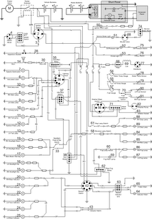
Spent some time yesterday night working out what most of the components actually do. Here are my findings, along with a new version of the military circuit diagram.
 6-Way lighting switch
Note that the lighting switch is not supplied via the ignition switch, so some lights will work when the ignition is off.
Supply to the light switch is direct from the battery, via the infra red relay.
Six connections:
- Stop lamp, hazard switch, aux relay (NY)
- IR Switch (UB)
- Tail Lamps (RB)
- Side lamps, dash illum (RY)
- Convoy lamp (RY)
- IR Relay (NP)
Six modes of operation (unconfirmed):
- Off
- (T) Tail lamps
- (ST) Side and tail lamps
- (HST) Head, side and tail lamps
- (Conv) Convoy lamp
- (S. Conv) Convoy and side lamps?
Infra Red Switch and Relay Used to switch off entire lighting system when using IR lights. Controls supply to main lighting switch.
IR relay activated by IR switch. Supply direct from battery. Feeds main lighting switch.
IR switch supplied directly from battery. When in “Headlights Normal” position, activates head lights (via flash and dip switch), auxiliary relay and fog relay (pins 1, 2 and 3 connected). When in “Infra-Red” position, links lighting switch to headlight flash and dip switch (pins 1 and 5 connected).
Auxiliary Relay The aux relay activates things which need to be on when the ignition is on AND the light switch says it’s OK!
Activated by lighting switch, on same supply as stop lights and hazard switch (for hazards) Supply from ignition switch Supplies headlight flash switch, horn, reverse lamps and hazard switch (for indicators).
Fog Relay When lighting switch enables the aux relay AND headlights are on, enables supply to fog lamp switch and thus fogs.
Hazard Switch and Flasher Supply for indicators comes from aux relay (so they’ll work if the ignition is on and the lighting switch allows). When hazard switch is OFF, power supplied to flasher pin 49 (the indicator supply). Flashing output from the flasher 49a feeds the indicator switch and thus the indicators.
Supply for the hazard lights comes from the lighting switch (so they’ll work if the lighting switch allows, but regardless of ignition switch position). When hazard switch is ON, power supplied to flasher pin 30b (the hazard supply). Pin 49a of the flasher is connected directly to the indicators, bypassing the indicator switch.